Autonomous Intruder-Detecting Drone
n7729697/drone-project · KTH DD2419 — Project Course in Robotics and Autonomous Systems · Group 6, four students · January – May 2022
A semester-long robotics project course at KTH. Each group is handed a Crazyflie 2.0 — a 27-gram nano-quadcopter with a monocular camera and an optical-flow deck — and a room, and has to make it fly itself. Our brief: patrol a known indoor world, work out where you are from the traffic signs on the walls, and report any sign that is not on the map as an intruder.
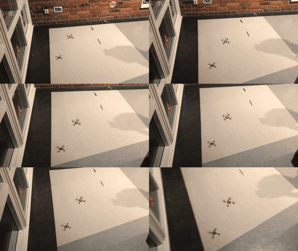 The final system. The drone holds altitude on the flow deck, follows a planned patrol, and reads
the signs on the wall as it passes.
I worked on localization, path planning and the brain — the parts that decide where the drone thinks it is and where it goes next. Perception was built by two teammates and is summarised further down. This page is weighted accordingly.
The problem, and why it is harder than it looks
The Crazyflie has no GPS, no lidar, and no external motion-capture rig. It knows two things: what its optical-flow deck says it has drifted since take-off, and what its single forward camera can see. Optical flow integrates, so its error integrates too — fly for a minute and the drone’s idea of its own position has walked away from reality.
The fix is to bolt the odometry to something absolute. The world contains ArUco markers and fifteen
classes of traffic sign (stop, roundabout, airport, no_bicycle, residential,
no_heavy_truck, narrows_from_left, …), and the map says where each one should be. Every time the
drone recognises a sign it knows where it is and gets a free check on whether that sign belongs
there at all. Localization and intruder detection turn out to be the same measurement read two
different ways.
System overview
Three subsystems and a brain, talking over ROS topics:
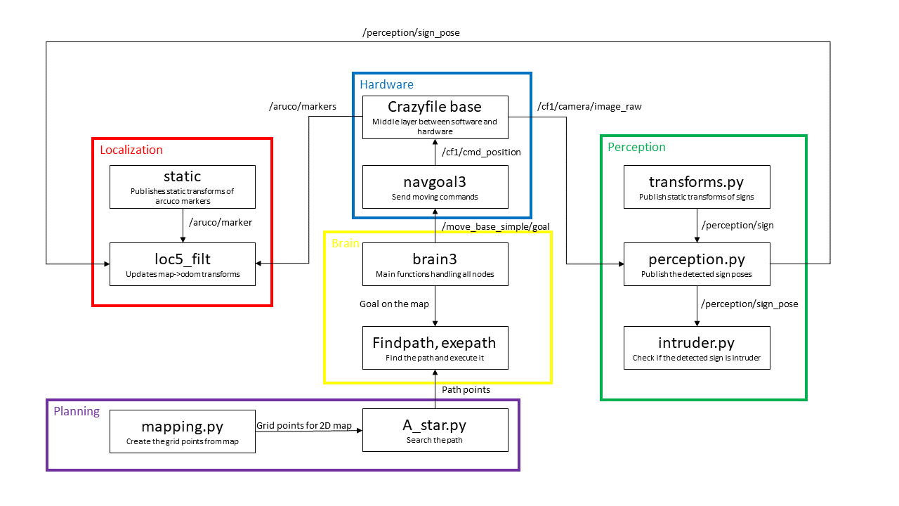 The node graph. Red is localization, green perception, purple planning, yellow the brain, blue the
Crazyflie hardware layer. Arrows are ROS topics.
Localization
loc5_filt is the node that answers “where am I on the map?”. It subscribes to two topics —
/aruco/markers from the ArUco detector and /perception/sign_pose from the perception stack — and
publishes the map → odom transform that anchors the drone’s drifting odometry frame to the world.
The design decision worth explaining is that ArUco is used exactly once. At start-up the drone
needs an unambiguous fix, and ArUco markers give one: each carries its own ID, so there is no data
association problem. Once that initial map → odom transform exists, the ArUco detections are
dropped and the node localises from traffic signs alone — which is the interesting case, because
signs are what the real world actually has on its walls.
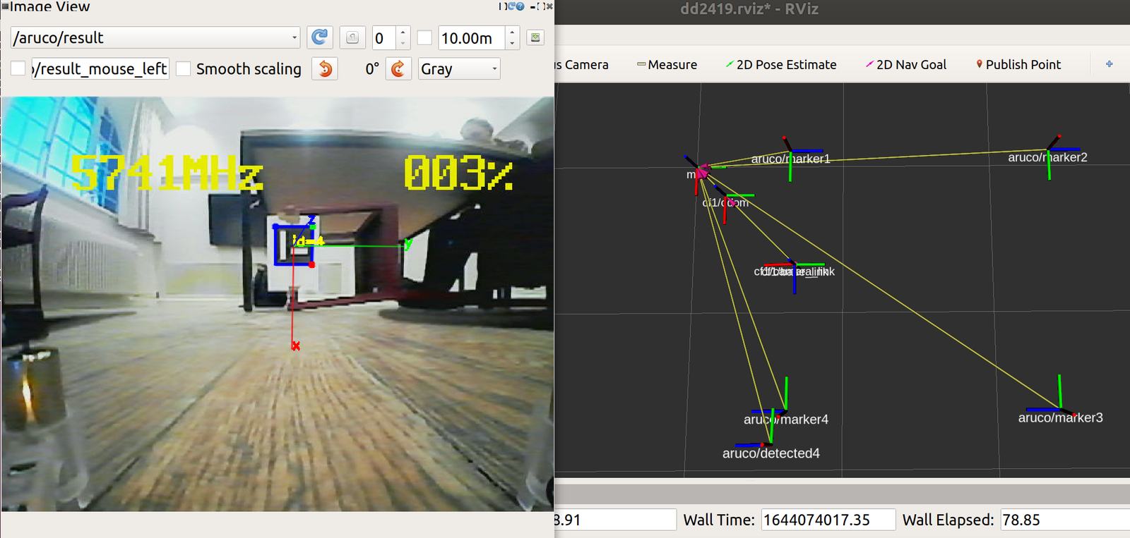 Bootstrapping. Left: a marker detected in the camera stream. Right: the resulting TF tree, with the
detected marker pose sitting next to where the map says that marker should be — the gap between the
two is the odometry error being corrected.
For each detection the node takes the camera_link → sign transform, looks up that sign’s known pose
on the map, and multiplies the two to recover map → odom. Three things keep this usable:
- Averaging. A single detection is noisy, so the node averages the five most recent transforms before publishing.
- Memory. When no sign is in view — most of the time, during a turn — it holds the last good transform rather than letting the estimate collapse.
- A rejection filter. Even averaged, the raw result jumped around more than expected. Pose estimates from bad detections, and the large apparent drift produced when the drone rotates, are filtered out before they reach the average. This filter was the difference between a localization that looked plausible in RViz and one the planner could actually fly on.
Path planning
Planning happens in two nodes. mapping.py converts the world description into an occupancy grid —
walls and the outer air boundary become occupied cells, everything else is free — with each cell
connected to its eight neighbours. a_star.py then searches that grid.
Plain A* off the shelf does not fly well on a map like this. The grid resolution, the cost function and the heuristic all had to be retuned together: too coarse a grid and the path clips a wall, too fine and the search crawls; a heuristic tuned for a square grid behaves badly on an 8-connected one where diagonal moves are cheaper than they look.
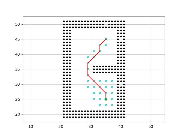 A* on the grid map. Black cells are walls and boundary, cyan crosses are expanded nodes, the red
line is the returned path. The search stays tight around the corridor rather than flooding the room —
that is the retuned heuristic doing its job.
The planner returns the path as 2-D poses at turning points only, not as every grid cell. That keeps the drone from stuttering along a staircase of tiny waypoints, and makes the path cheap to publish and inspect.
Execution goes through navgoal3. The obvious implementation is to publish poses straight to
/cf1/cmd_position, and it is the wrong one: cmd_position is expressed in the drifting odometry
frame, so the drift the localization node just corrected gets reintroduced with every command.
navgoal3 instead takes goals in the map frame from /move_base_simple/goal and converts them
at the moment of sending, so each command is issued against the freshest available estimate.
The brain
brain3 sequences everything:
- Hover in place until an ArUco marker is visible and localization initialises.
- Hold for four seconds — long enough for the averaged transform to settle before trusting it.
- Pick observation points on the map, chosen so that the patrol sees every sign it needs to.
- Plan the shortest path between successive observation points.
- Fly it, detecting signs along the way, and publish the path as a message so the rest of us could see in RViz what the drone thought it was doing.
That last point sounds like a detail and was not. Publishing the planned path as a visualisable topic was the single most useful debugging decision in the project — it made the difference between “the drone flew somewhere strange” and “the planner returned this, and the drone followed it”.
Perception
Built by Mattias Hansson and Marcus Rickenlund; summarised here for completeness.
Sign detection runs a pre-trained MobileNetV2 backbone with a 1×1 convolution producing a 20×15×5 tensor — per grid cell, a confidence that a bounding-box centre falls in it, plus the box’s relative centre, width and height — and a further 15 channels for the sign classes. Input is downsized to 200×200 for speed, and training used blur and colour-jitter augmentation on images captured from the drone’s own camera.
Pose comes from classical vision rather than the network: SIFT keypoints from the detected crop are
cross-matched by k-nearest-neighbours against reference images of each sign, then PnP RANSAC
recovers the 6-D pose, published on /perception/sign_pose.
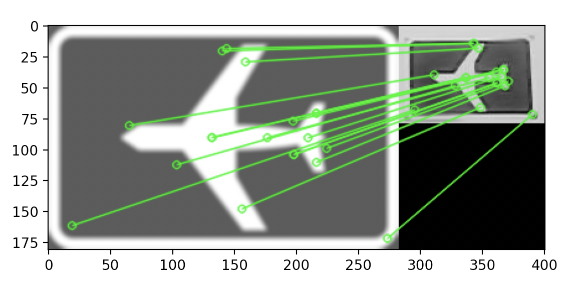 SIFT correspondences between the reference airport sign (left) and the crop from the drone camera
(right). These matches are what PnP turns into a 6-D pose.
intruder.py closes the loop: it compares each detected sign pose against the signs the map says
should exist, and anything left over is an intruder.
The system running
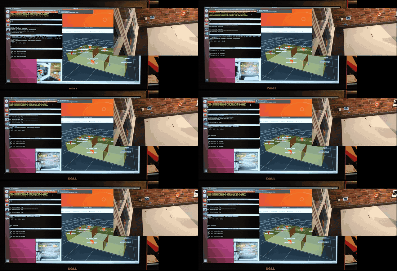 Everything at once. RViz shows the world model with the mapped signs labelled and the drone’s pose
updating; the terminal logs detections and intruder decisions; the inset is the drone flying the
patrol in real time.
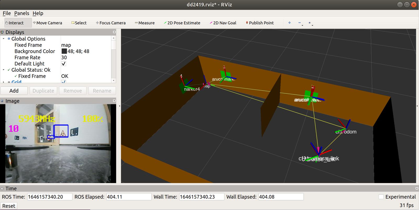 A closer look at the same thing mid-flight: live camera with a sign bounding box on the left, and
the map, marker poses and full TF chain —
map, cf1/odom, cf1/base_link, cf1/camera_link — on
the right.
What was hard
- Optical-flow odometry drifts, and drifts unevenly. The flow deck wants floor texture. On the wooden floor of our test space, tracking was noticeably better perpendicular to the planks than parallel to them — the sensor is happiest with checkerboard-like patterns, and long parallel lines give it much less to lock onto. That anisotropy is not in any datasheet; we found it by flying the same square in two orientations.
- The ArUco markers were printed at the wrong size, and the marker-size setting in
base.launchwas only discovered later. Early detections were therefore consistently off by a scale factor, which looked exactly like a localization bug and was not. - Sign-based localization was jumpier than expected, which is why the averaging and the rejection filter exist at all. The first version, publishing raw transforms, was unusable.
- Milestone 3 slipped. The drone could not yet take off from a known position with a landmark in view, and it did not fly the executed path smoothly. We spent time in the course’s daily-reporting “monitoring mode” reworking the take-off sequence and the path execution before both were signed off. It was the right catch — the take-off fix is what made the data association problem tractable at all.
- COVID. A chunk of the early work happened at home, where there was no arena and the flow deck had nothing useful to look at, which cost us the first milestone.
My role
- Localization — the
loc5_filtnode: the ArUco-bootstrap-then-signs-only design, the transform chain, the five-frame averaging and the rejection filter. - Path planning — the grid conversion and the A* search, including the cost and heuristic tuning, and the turning-point-only path representation.
- The brain — sequencing the subsystems, and the integration work that made planning and localization cooperate rather than fight. In the group’s own words from the Milestone 3 report: “NIU mainly contributes on the integration of planning and localization in brain and normalization of the map and planner in whole system.”
- Running the integrated system. The full stack was run and tested on my machine for most of the project, which meant I was usually the one holding the whole thing in view when a subsystem changed.
Early on the split was pairwise — Pascal and I on localization, Mattias and Marcus on perception — and it converged as the parts had to be integrated.
Team and repository
Group 6: Xuezhi Niu, Pascal Jaufmann, Mattias Hansson, Marcus Rickenlund.
Code lives at github.com/n7729697/drone-project,
my fork of the group’s shared repository. It is a ROS workspace: localization/, pathplanning/,
perception/, brain/ and world/, plus the world descriptions we flew against. It is student
code written to a deadline — the README is a list of rosrun commands, not documentation — but it
is the real thing, and it flew.