Electronically Vacuum Regulated Shut-off Valve for Milking Systems
Full report — DiVA, 95 pp. · DeLaval International AB · KTH Mechatronics Advanced Course (MF2058 / MF2059) · March 2022 – January 2023
A capstone project on the Mechatronics track at KTH, run with DeLaval International AB as the stakeholder. Eight students, one academic coach and two industrial coaches spent close to a year on one narrow question: during machine milking, why does the vacuum at the cow’s teat collapse exactly when the milk is flowing fastest, and can a valve be built that holds it steady?
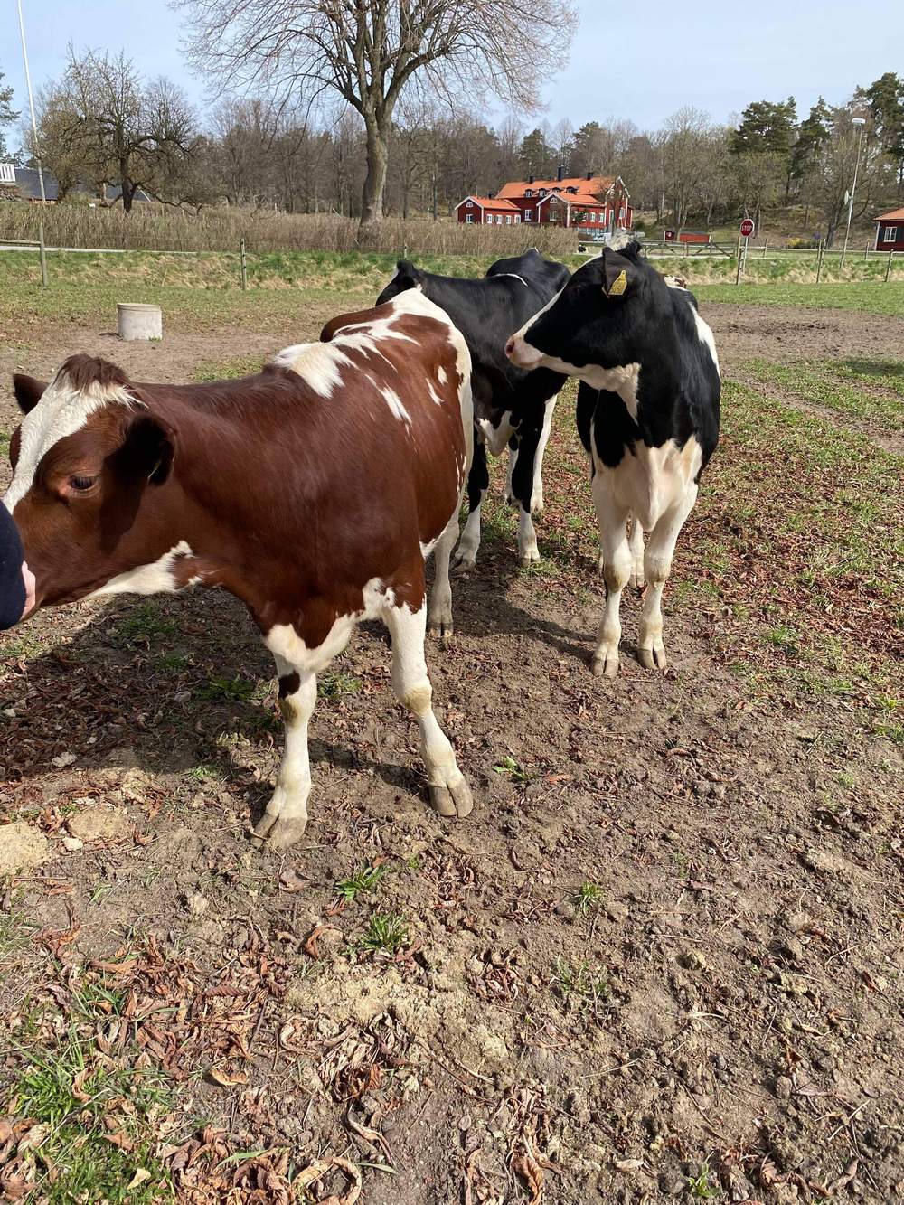 March 2022 — the stakeholder visit, where the problem is still a cow in a field. |
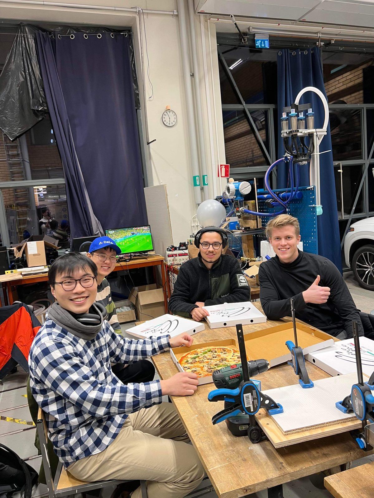 December 2022 — the rig behind us, the World Cup on the monitor, the report still unwritten. |
|---|---|
 November 2022 — outside the lab. |
 The stretch in between, which is most of what a capstone actually is. |
The problem
A milking cluster is held to the teats by vacuum, and the same long milk tube that supplies that vacuum also carries the milk away. Those two jobs fight each other. As milk flow rises, the vacuum measured at the cluster falls — and the literature is consistent that it is the minimum cluster vacuum, not the nominal system vacuum, that governs milking performance and teat condition. Teat tissue is stressed most at low flow, when teat-end vacuum is highest; milk removal suffers at high flow, when it is lowest.
DeLaval’s existing shut-off valve is a mechanical diaphragm that reacts to the difference between a control vacuum and the milk-tube vacuum. It works, but it self-oscillates, it regulates imprecisely, and it has a vacuum drop designed into it. The brief was to replace it with something electronically regulated, sensed, and closed-loop — while staying modular, cheap, and inside food-contact regulations (ISO 5707:2007).
Why the drop cannot be designed away
Before choosing a valve, it was worth establishing what a valve could and could not do. Starting from Bernoulli’s equation, the vacuum drop along a milk tube is
\[\Delta P = (1-\alpha)\rho_m g H + (1-\alpha)\lambda \rho_m \frac{L_t}{D}\frac{u_M^2}{2} + (1-\alpha)\xi \rho_m \frac{L_t}{D}\frac{u_M^2}{2},\]where $\alpha$ is the volumetric air coefficient in the long milk tube, $u_M$ the reduced velocity of the milk–air mixture, and $\lambda$, $\xi$ the linear and local loss coefficients. Substituting Golisz et al.’s expression for $\alpha$ and collecting terms in the drop itself, $x = \Delta P$, reduces the whole thing to a quartic:
\[\varepsilon_4 x^4 + \varepsilon_3 x^3 + \varepsilon_2 x^2 + \varepsilon_1 x + \varepsilon_0 = 0 , \qquad \varepsilon_0 > 0 .\]Because the constant term $\varepsilon_0$ is always strictly positive, the polynomial has no zero root. The vacuum drop is never zero — not for any tube geometry, any valve design, or any flow rate. It can only be compensated, by deliberately putting a controlled restriction downstream and giving up some system vacuum to hold the cluster where you want it. That result set the scope of the project: this was a control problem wearing a mechanical-design costume. The full expansion, including the bubble-rise velocity term and its assumptions, is in Appendix A.1 of the report.
The valve
Of the two concepts evaluated — a pinch valve and a solenoid–diaphragm hybrid — the pinch valve won, largely on hygiene. A pinch valve has an elastic sleeve as its only wetted part: no internal mechanism, no dead volume, no small chambers where milk residue can sit.
The twist is that ours runs inverted. A conventional pneumatic pinch valve is squeezed shut by positive pressure in its chamber. Here there is no compressed air available — but there is vacuum everywhere. So the chamber is held at atmospheric pressure to let the sleeve collapse shut, and evacuated to open it. Actuation therefore comes free from the vacuum the system already has, and the control signal is itself a vacuum level.
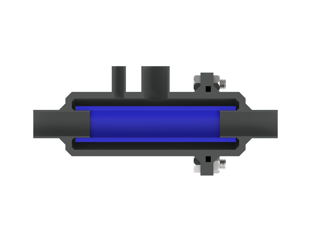 Chamber evacuated: the sleeve is pulled open and flow passes almost unobstructed. |
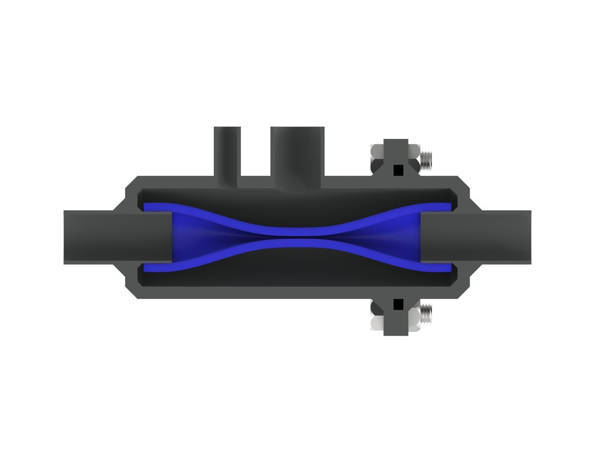 Chamber at atmospheric pressure: the pressure deficit inside the sleeve collapses it shut.
:————————-:|:————————-:
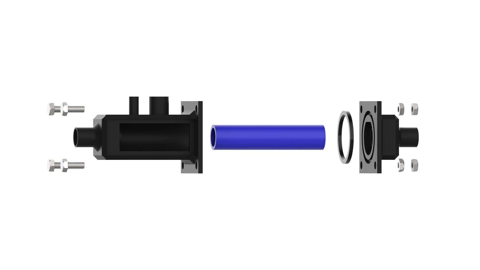 Exploded view — chamber body, sleeve, O-ring, end flange. The sleeve is a length of milk-line tubing,
sanded down until it collapsed readily under the pressure deficit. Bodies were 3D-printed in PLA for
the prototype; the geometry is food-safe even though the material is not.
Sensing and control
Two pressure sensors and one flow meter. The controller sensor sits just upstream of the valve — deliberately as far from the cow as possible, since cows kick clusters off and stand on milk tubes — and the relationship between what it reads and the actual cluster vacuum was calibrated as a linear function of flow. The cluster sensor was used for verification, not for control.
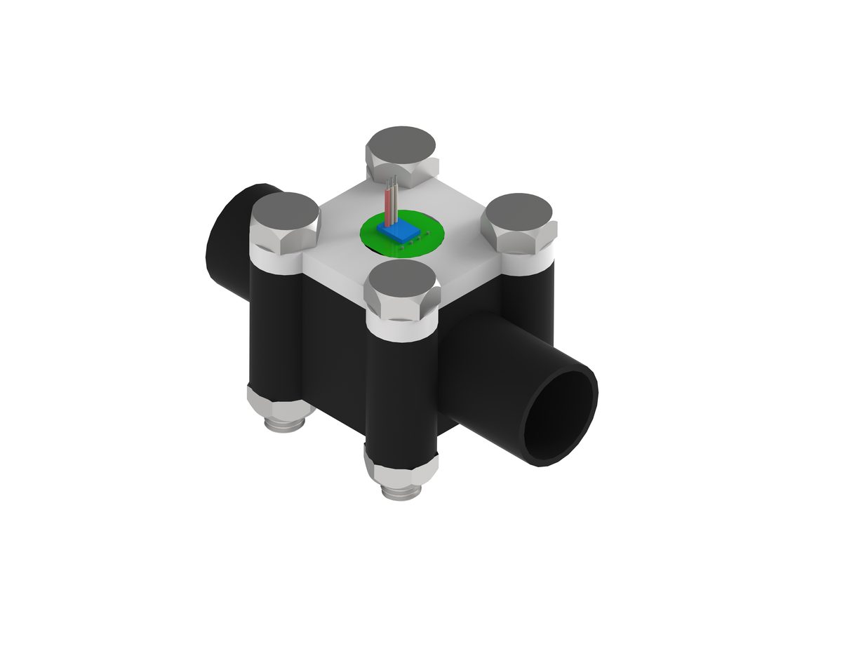 Sensor housing. Like the valve, no internal cavities: it is a section of tube with a port, so it cleans in place. |
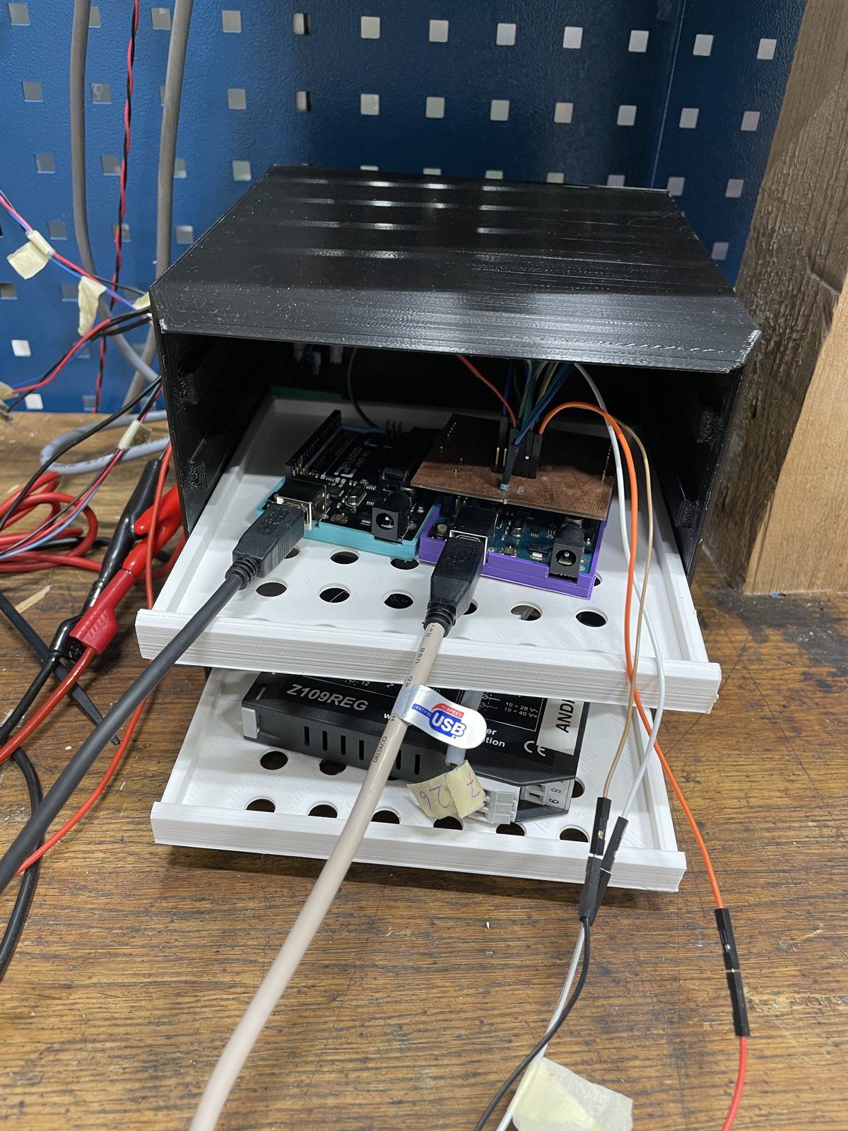 The controller box — Arduino, regulated supply and signal conditioning in a printed enclosure.
:————————-:|:————————-:
Control is a cascade: an outer loop regulating cluster vacuum to its reference, and an inner, much faster loop regulating the pinch chamber vacuum to whatever the outer loop asks for. System identification never produced a model good enough for honest pole placement, so the two loops were tuned empirically to keep roughly the standard factor-of-ten separation in bandwidth. Raw pressure readings were noisy enough to need filtering before they were usable as feedback or as evidence — a Kalman filter on the sensor stream, and a 3-second rolling average on the figures below.
The test rig
The stakeholder requirement was blunt: build a rig so the students can test at KTH instead of commuting to DeLaval. So we did — a full low-line milking loop with vacuum pump, cluster, water divider, milk meter, valve and sensors, running water instead of milk (close enough in the properties that matter here) at a system vacuum of 55 kPa.
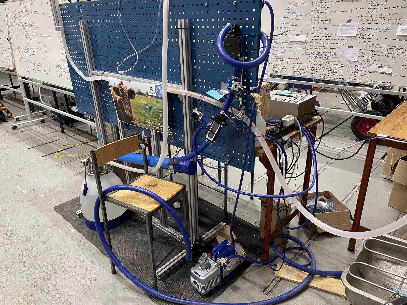 The rig in December 2022. Vacuum pump at floor level, cluster and divider mid-frame, the inverted
pinch valve and sensor housing on the blue line. The whiteboard behind it is the report outline.
Every measurement below comes off this rig. Tests were designed in pairs, so each figure isolates one variable: the same flow ramp with the controller off and on; the same flow band across the existing valve and the new one.
Results
The problem, then the fix. In both runs the flow (green) is ramped from zero up past 11 L/min against a fixed reference (purple, 44 kPa here). Open loop, the pinch chamber (blue) sits flat — the valve is simply held open — and the cluster vacuum (yellow) sags by more than 10 kPa as flow rises. Closed loop, the controller walks the chamber vacuum up as flow increases, and the cluster stays on the reference.
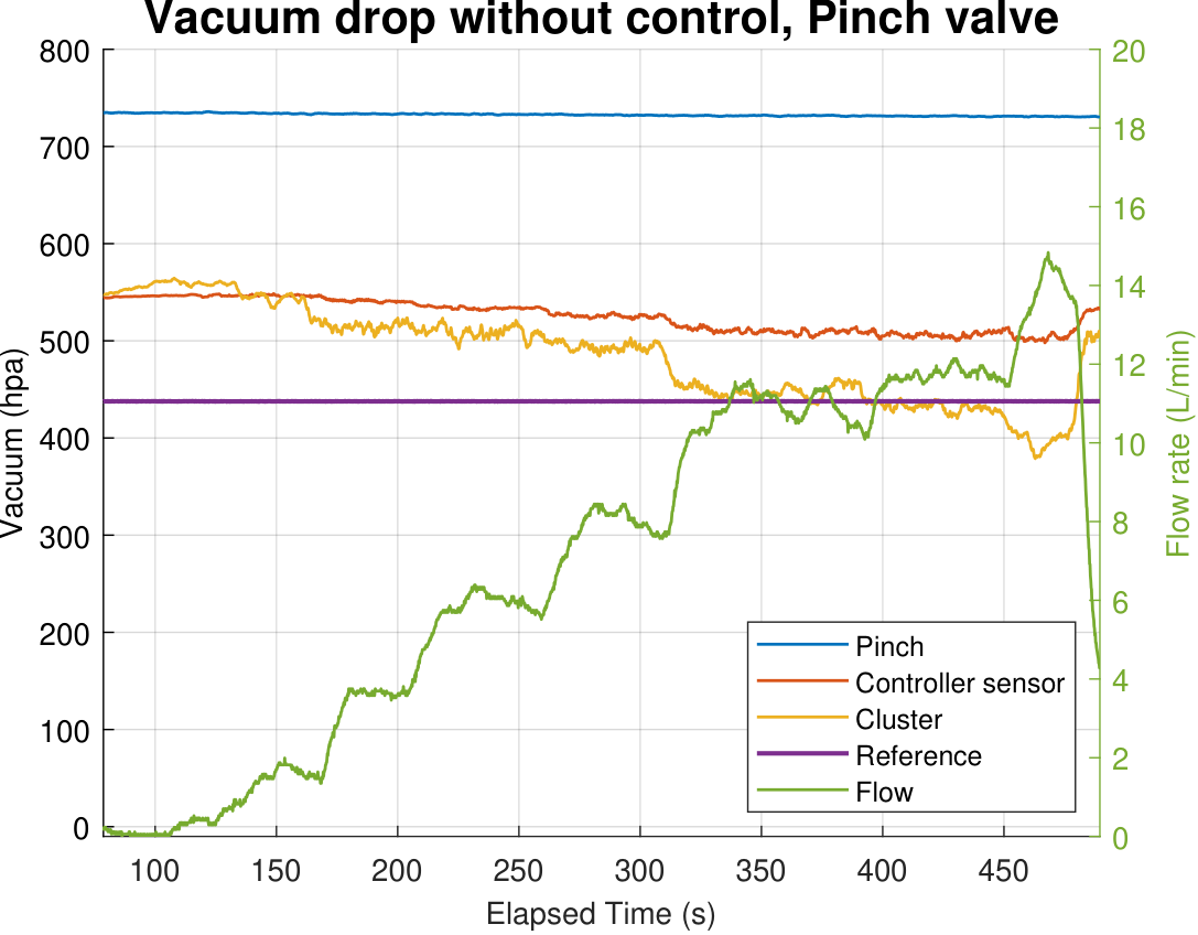 Controller off: cluster vacuum falls steadily as flow rises. |
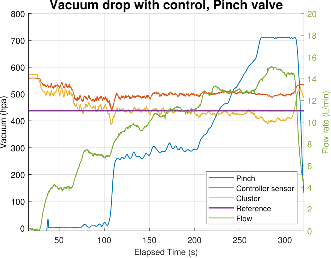 Controller on: the chamber vacuum rises with flow and the cluster holds the reference.
:————————-:|:————————-:
Tracking error, and where it runs out. The headline figure, and the honest one. Below roughly 6 L/min the deviation from reference is +10 to +14 kPa: the sleeve cannot seal completely, so the cluster vacuum stays stubbornly too high. Above that, the error collapses to a band of a few kPa around zero and stays there until the flow exceeds about 12 L/min, at which point the valve is fully open and there is nothing left to give.
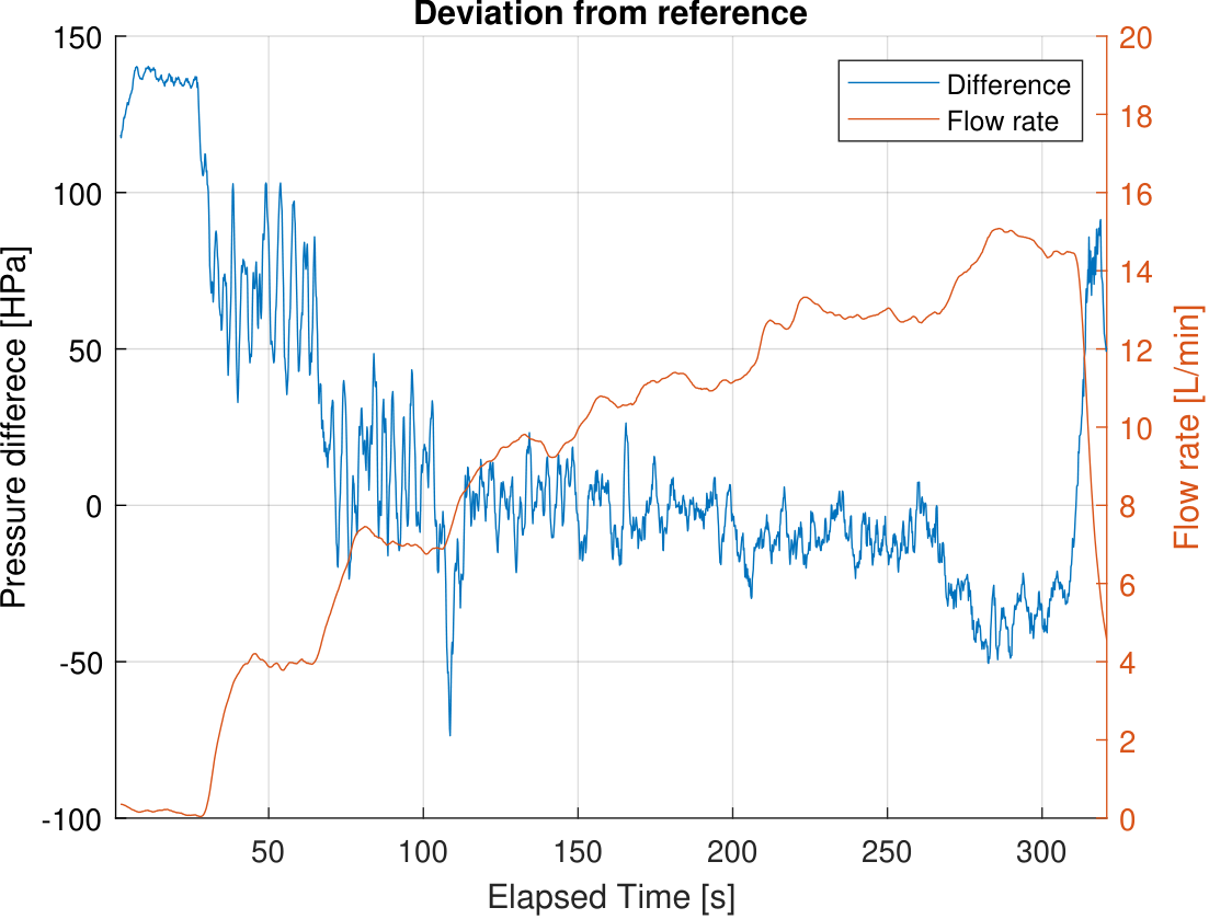 Deviation of cluster vacuum from reference (blue) against flow rate (orange). The controllable band
is 6–12 L/min at a 45 kPa reference, with a 55 kPa system supply.
Drop across the valve itself. Both plots share the same axes. The existing diaphragm valve costs around 2 kPa at 12–13 L/min; the inverted pinch valve costs 0.5–1 kPa over 10–14 L/min, and 0.8 kPa at an averaged 10.2 L/min — inside the 1 kPa the stakeholder asked for. This is the one result where the pinch geometry wins outright: when it is open, it is just another piece of tube.
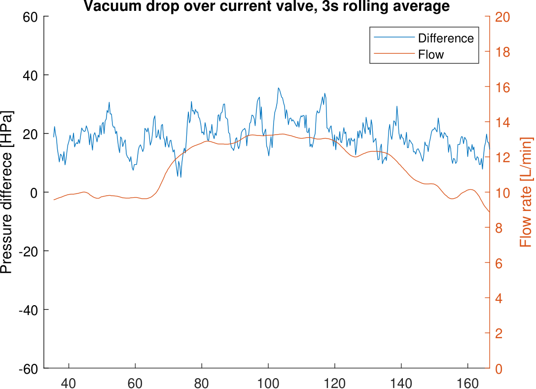 Existing valve: roughly 2 kPa at 12–13 L/min. |
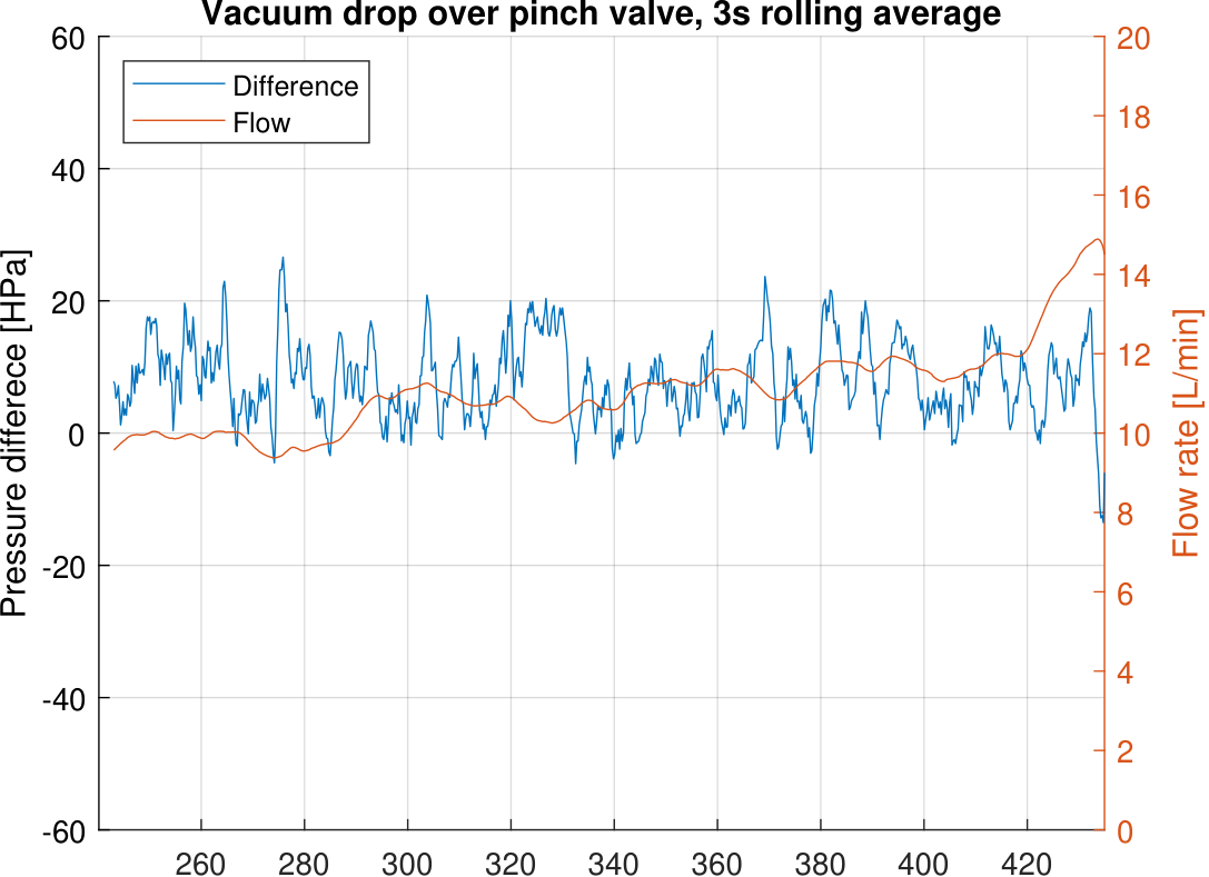 Inverted pinch valve: roughly 0.8 kPa over the same band.
:————————-:|:————————-:
Edge case: teat-cup slip. A teat cup was deliberately misaligned to leak air mid-run. The cluster vacuum plunges, the controller drives the chamber to full open, and the cluster is back on reference within about forty seconds.
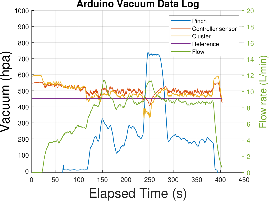 Emulated slip at ~245 s. The controller recovers, though the whole system lost about 10 kPa while
the leak was open.
Against the requirement list: 11 requirements fulfilled, 2 partially, 1 not met, 2 untested.
What did not work
Worth stating plainly, because it is where the interesting engineering is:
- Below 6 L/min the valve cannot close tightly enough. A small flow always passes, so the cluster vacuum sits above reference and the ±1 kPa requirement for 0–10 L/min was missed. The sleeve was a sanded-down piece of milk tubing; its optimal wall thickness, length and profile were never characterised. A thinner or longer sleeve very likely closes this gap.
- Above 12 L/min there is no headroom. The valve is already fully open, so raising cluster vacuum further would need a higher system supply — and the supply was capped at 55 kPa by the stakeholder. In practice a milking session only spends a short time this high.
- The pump could not ride out a large leak. During the slip test the entire system lost 10 kPa. Since the only way the controller can raise cluster vacuum is by opening the valve and letting system vacuum through, a system-wide loss slows recovery. That is a pump sizing problem, not a control problem.
- PLA is not food-safe. The prototype geometry satisfies ISO 5707:2007; the printed material does not. Production parts would be moulded the same way DeLaval’s current valve is.
One design observation that outlived the project: since the cluster vacuum drop is a function of both flow rate and the upstream sensor reading, a sufficiently well-characterised system could infer cluster vacuum from pressure alone — and drop the flow meter entirely.
My role
I worked mostly on the analytical, experimental and organisational side of this project:
- Derived the vacuum-drop model and the quartic argument above, establishing that the problem could not be solved by geometry and had to be solved by control. This framed the concept evaluation.
- Drafted and edited the report — the 95-page document that became the DiVA publication.
- Ran the planning: milestone structure, the Kanban board, and the timeline that kept eight people and four parallel workstreams converging on one December deadline.
- Helped build the test rig, and designed the test matrix — deciding what each run had to isolate for the results to mean anything.
- Collected and analysed all the measurement data.
- Wrote all of the MATLAB: serial acquisition from the Arduino, the Kalman filter and rolling average on the pressure streams, and every plot in the report, including the six above.
Team and acknowledgements
The result belongs to the team. The valve body and sensor housing CAD, the renders, the firmware and much of the mechanical build were other members’ work, and the project only held together because eight people kept showing up to a cold workshop through a Stockholm autumn.
Team: Carl Egenäs, Felix Ekman, Chenqi Ma, Tim Naser, Xuezhi Niu, Axel Sernelin, Samuel Stenow, Benjamin Ström. Project leads: Samuel Stenow (spring), Axel Sernelin (autumn).
Academic coach: Nils Jörgensen, KTH Mechatronics. Industrial coaches: Daniel Brun and Andreas Edmark, DeLaval International AB.
With thanks to the KTH Mechatronics department for the workshop, the vacuum pump, and a good deal of patience.
Egenäs, Ekman, Ma, Naser, Niu, Sernelin, Stenow & Ström (2023). “Electronically Vacuum Regulated Shut-off Valve for Milking System.” KTH School of Industrial Engineering and Management, 95 pp. urn:nbn:se:kth:diva-324226