SinEnergy (信能) — a Safe, Flexible Nickel-Based Wristband Battery
City University of Hong Kong, Department of Mechanical Engineering · Team project, 2018–2019 · Supervisor: Dr. ZHANG Kaili · Project lead: Dr. YANG Shaoran (PhD)
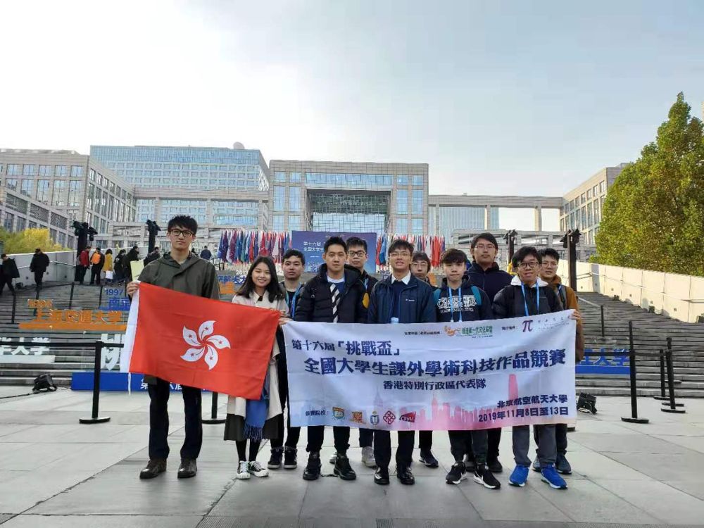 The Hong Kong delegation at the 16th “Challenge Cup” National Finals, Beihang University, Beijing, November 2019. Photo: team archive.
Summary
Wearables need batteries that bend, survive sweat, and sit against skin for hours. The lithium-ion cells that dominate the market are not a comfortable answer: they use flammable organic electrolyte, and a cracked flexible pouch next to skin is a real hazard. SinEnergy chose a different, boring-on-purpose platform: water-based nickel chemistry (Ni–MH and battery-type supercapacitors, KOH electrolyte), whose materials, coaters and rolling mills already exist in factories that make cylindrical Ni–MH cells.
The project had two technical halves, and one business half that tied them together:
- A flexible battery structure and its assembly and packaging: a thin sandwich of electrodes and gel electrolyte, and three ways to seal it so that it bends and stays waterproof.
- A high-mass-loading multi-component metal hydroxide (NCMH): a seed-assisted hydrothermal route that grows Ni–Co–Mn hydroxide nanoflakes directly on Ni foam, with no binder.
- Innovation and entrepreneurship: a product prototype (a wristband), a cost and margin model, a risk analysis, and a pitch that won prizes at three competitions.
Recognition
| Date | Competition | Result |
|---|---|---|
| 2019.04 | 5th Hong Kong University Student Innovation and Entrepreneurship Competition (HK SAR) | Second Prize |
| 2019.10 | National Finals of the “Internet+” Competition (Hangzhou) | Silver Prize |
| 2019.11 | National Finals of the 16th “Challenge Cup” (Beijing) | Second Prize |
Earlier steps on the same road (from the project’s own record): NBI 2018 innovation and entrepreneurship invitational, North-East China Top 10 (Dalian, 2018.06); JUMPStarter Startup 2019 Hong Kong International University Student Startup Competition, Top 20 (2019.01).
Credit and scope. This was a team effort. The proposal lists YANG Shaoran (project lead), NIU Xuezhi, CUI Haozhe, ZHANG Dingyu, TSANG Ying and Dr. ZHANG Kaili. The seed-assisted hydroxide chemistry grew out of Dr. Zhang’s group and the final year project of TSANG Ying (A General Approach to Prepare High Mass-Loading Electrodes for Supercapacitor Applications, April 2018, supervised by Dr. Zhang with guidance from Mr. Yang). I contributed on the structural and product side and in the entrepreneurship work. Section 6 states what I can document and what I have not documented here.
1. Why a nickel-based flexible battery
| Li-ion (polymer pouch) | Ni–MH / battery-type supercapacitor (this project) | |
|---|---|---|
| Electrolyte | flammable organic solvent | aqueous KOH (gel) |
| Failure when cut or punctured | leakage, fire possible | leakage of mild alkali, no fire |
| Energy density | high | lower (see Section 4) |
| Cost | high | low |
| Manufacturing | specialised dry-room lines | reuse existing Ni–MH lines: same Ni foam, KOH, mixers, coaters, rolling mills |
The trade-off is explicit: we give up energy density and buy safety, water-tolerance, cost and manufacturability. For a wristband, a torch or a low-power display this is the right trade. For a phone, it is not. Stating the limit early was part of the pitch, because judges notice who has understood their own weakness.
Product ladder. The plan had three product types:
- Type I (Ni–MH): industrial Ni–MH electrode sheets, re-packaged flexibly. Fast to industrialise.
- Type II (battery-type supercapacitor): our NCMH positive electrode and a hierarchical carbon negative electrode, with a flexible nickel-paper current collector. Better performance, more academic value.
- Type III (self-charging, in research): Type II plus a piezoelectric energy-harvesting layer (PZT foam composite) so that arm motion tops up the cell.
2. Part A — flexible battery structure, assembly and encapsulation
2.1 The sandwich
| The device is an all-solid-state sandwich: positive electrode | PVA/KOH gel | negative electrode, where the gel is both electrolyte and separator. |
- Gel electrolyte: 3 g PVA and 5 mL of 6 M KOH in 25 mL of deionised water at 90 °C. The two electrodes are dipped in the cooled gel, laid parallel, and dried until the gel solidifies.
- Positive electrode (Type II): NCMH on Ni foam (Section 3).
- Negative electrode: hierarchical porous carbon (HPC) from corn cob (Section 3.4), slurry-coated at 8 : 1 : 1 (HPC : PVDF : acetylene black) in NMP, on Ni foam or on flexible nickel paper, vacuum dried at 100 °C for 6 h.
- Flexible current collector, “nickel paper” (NFIP): a thin nickel film grown hydrothermally (165 °C, 9 h; PVP, ammonia, nickel nitrate and hydrazine) on a textured silicon wafer used as a template, then peeled off. The pyramid texture gives the film an inverted-pyramid micro-morphology, which is what makes it more bendable than a flat foil of the same material.
2.2 Why bending is a design constraint, not a test
For a laminate of total thickness $t$ bent to radius $R$, the outer-fibre strain of a symmetric stack is approximately
\[\varepsilon \approx \frac{t}{2R}.\]For an illustrative stack $t = 2$ mm on a wrist-sized radius $R = 20$ mm, $\varepsilon \approx 5\%$, which is already large for brittle ceramic-like active layers and for solder or tab joints. Three design rules follow:
- Keep the stack thin and keep stiff layers near the neutral axis.
- Avoid a binder-and-powder film that cracks. Growing the active material directly on the conductive skeleton (Section 3) means there is no separate coating to delaminate.
- Put the weld tab outside the bending zone.
2.3 Three encapsulation routes (from the proposal)
| Route | Method | Where it fits |
|---|---|---|
| 3M 4910 VHB acrylic tape | Two pieces slightly larger than the electrode pair, laid face to face, self-adhesive seal; remove the liner and rinse | Fast lab prototypes and demos |
| PE/nylon composite pouch | One piece around the electrode stack, heat-sealed under vacuum, excess trimmed | The closest to a factory process |
| Parafilm | Two sheets over the stack, held flat between glass plates, 150 °C for 1 h, cooled, trimmed | A cheap, transparent, flexible seal |
The proposal’s demonstrations include powering an electronic watch under water, which is the practical test that matters for a wrist product.
2.4 The assembly die and fixture
Placeholder, to be filled with the real drawing. The source files I have for this page (proposal, final year report, award material, photos) describe the process and the three seals, but contain no drawing or photograph of the assembly die itself. I have therefore not invented dimensions. A good figure here would be: (a) an exploded view of electrode / gel / electrode / seal; (b) the clamping plate that holds the stack flat during gel drying and during the Parafilm bake; (c) the tab-exit relief. Please send the CAD or a photo and I will add it with its design reasoning (clamp pressure, gap control, tab strain relief).
What the die has to do, from the physics above: hold the two electrodes parallel at a controlled gap while the gel gels (so the gel thickness, and thus the ionic resistance, is uniform), apply uniform light pressure during the 150 °C seal (so there are no trapped bubbles or wrinkles that become leak paths), and release without peeling the film.
3. Part B — high-mass-loading multi-component metal hydroxide
3.1 The problem: capacity per area, not only per gram
Most papers report gravimetric performance on a few tenths of a milligram per cm$^2$, where almost all active material touches the current collector. A real device needs high areal loading (several mg cm$^{-2}$); otherwise the current collector and packaging dominate the mass. But simply growing more material usually fails: thick layers lose contact, ions cannot reach the inside, and capacity per gram collapses.
The measure we care about links the two:
\[Q_m = \frac{Q_A}{m_A}\qquad\left[\text{mAh g}^{-1}\right],\qquad Q_A\ [\mu\text{Ah cm}^{-2}],\; m_A\ [\text{mg cm}^{-2}]\]A high-loading electrode is good only if $Q_A$ grows almost in proportion to $m_A$, so that $Q_m$ stays high.
3.2 Synthesis: a two-step, seed-assisted hydrothermal route
Step 1: seeds. Ni foam (about 3.5 cm × 6 cm) is cleaned ultrasonically in acetone and DI water and hung vertically in a PTFE-lined autoclave with 80 mL of solution containing 4 mmol Ni(NO$_3$)$_2\cdot$6H$_2$O and 16 mmol urea. Chemical bath at 100 °C for 12 h, then wash and dry at 80 °C. Result: a forest of Ni(OH)$_2$ nanorods standing on the foam.
Step 2: growth. The seeded foam goes into a fresh 80 mL solution containing 1 mmol each of Ni(NO$_3$)$_2$, Co(NO$_3$)$_2$ and Mn(NO$_3$)$_2$ and 16 mmol urea, at 100 °C for 10 h. Result: Ni–Co–Mn hydroxide (NCMH) nanoflakes on the foam. The loading series varies all three nitrates at 0.8, 1.0 and 1.2 mmol.
Chemistry. Urea hydrolyses slowly on heating,
\[\mathrm{CO(NH_2)_2 + 3\,H_2O \;\rightarrow\; CO_2 + 2\,NH_4^+ + 2\,OH^-},\]so the pH rises gradually and uniformly, and the metal ions precipitate as hydroxides,
\[M^{2+} + 2\,\mathrm{OH^-} \;\rightarrow\; M(\mathrm{OH})_2 .\]With 16 mmol urea there is a large excess of potential hydroxide (up to 32 mmol) over the 3 mmol of metal in step 2, so growth is limited by supply of metal, which is how the three loading levels (0.8, 1.0, 1.2 mmol) control the loading.
Why seeds help. Without seeds, nucleation on a smooth skeleton is sparse and the flakes grow as loose, poorly attached clumps. The Ni(OH)$_2$ nanorods provide many pre-formed nucleation sites that are chemically similar to the product, so the nanoflakes grow upright from the seeds, attached to the foam, with open channels between them. That gives three things at once: adhesion (no binder), electron path (flake to rod to foam), and ion access (open, 20–30 nm-thin flakes).
3.3 Structure and performance (from the proposal’s characterisation)
- SEM: uniform, vertically oriented nanoflake arrays on the foam; flake thickness about 20–30 nm, little variation.
- TEM/HRTEM: mesopores of 2–3 nm in the thin parts of the flakes; lattice spacing 0.235 nm, assigned to the (101) plane of the hydroxide (JCPDS 14-117); EDX maps show Ni, Co, Mn and O distributed uniformly, evidence of a genuinely mixed, not phase-separated, product.
- Electrochemistry (three-electrode, KOH): at an active mass loading of 5.2 mg cm$^{-2}$ (1.0 mmol sample), the electrode delivers 1043.1 µAh cm$^{-2}$ at 2.5 mA cm$^{-2}$, equal to 200.6 mAh g$^{-1}$ at about 0.5 A g$^{-1}$.
| Areal current (mA cm$^{-2}$) | 2.5 | 5.0 | 7.5 | 10 | 15 |
|---|---|---|---|---|---|
| Areal capacity (µAh cm$^{-2}$) | 1043.1 | 952.8 | 873.6 | 805.6 | 708.3 |
| Gravimetric (mAh g$^{-1}$) | 200.6 | 183.2 | 167.8 | 154.9 | 135.4 |
| Retention vs 2.5 mA cm$^{-2}$ | 100% | 91% | 84% | 77% | 68% |
Consistency check, which I did myself: $1043.1/5.2 = 200.6$ mAh g$^{-1}$, and $2.5/5.2 = 0.48$ A g$^{-1}$, matching the stated “about 0.5 A g$^{-1}$”. The retention row is computed from the proposal’s numbers: a six-fold increase in current (2.5 to 15 mA cm$^{-2}$) keeps about 68% of the capacity. The GCD curves show a discharge plateau and a non-linear region around 0.25–0.5 V, which is the signature of Faradaic (battery-type) charge storage rather than ideal capacitive storage. The proposal also reports that the seeded NCMH has a longer discharge than the non-seeded counterpart and than the Ni(OH)$_2$ seeds alone at the same current.
3.4 The negative electrode and the full device
HPC from corn cob. Corn-cob woody ring is pyrolysed in argon (900 °C, 4 h), ground, then KOH-activated (KOH : C = 4 : 1 by mass, 900 °C, 2 h), washed in 3 M HCl and DI water, dried at 100 °C. The idea is hierarchical porosity: macropores (about 1 µm channels) inherited from the cob, mesopores (about 10 nm), and micropores created by activation. In 6 M KOH, three-electrode: 293, 278, 255, 228, 195 F g$^{-1}$ at 1, 2, 3, 4, 5 A g$^{-1}$ (CV: 299 to 227 F g$^{-1}$ from 1 to 20 mV s$^{-1}$), a near-rectangular CV and a small high-frequency arc in the Nyquist plot.
Asymmetric device HPC // NCMH (negative // positive), liquid electrolyte and all-solid-state gel version:
| Quantity | Liquid KOH | All-solid-state (PVA/KOH) |
|---|---|---|
| Specific capacitance at 1 A g$^{-1}$ | 96.4 F g$^{-1}$ | 76.7 F g$^{-1}$ |
| Energy density at 750 W kg$^{-1}$ | 28.55 Wh kg$^{-1}$ | 23.96 Wh kg$^{-1}$ |
| Energy density at 3000 W kg$^{-1}$ | 10.01 Wh kg$^{-1}$ | not reported here |
| Capacity retention after 5000 cycles at 2 A g$^{-1}$ | 81.4% | reported as 90.3% |
Two caveats a rigorous reader will want:
- Reading the Ragone numbers. At 750 W kg$^{-1}$, $28.55\ \text{Wh kg}^{-1}$ means a discharge of $t = E/P = 28.55/750\ \text{h} \approx 137\ \text{s}$; at 3000 W kg$^{-1}$, $10.01/3000\ \text{h} \approx 12\ \text{s}$. These are supercapacitor-class discharge times, not hours: this device is a power-oriented cell, and that is why the product story is a low-power wearable with energy harvesting, not a phone battery.
- The solid-state retention figure. The proposal text gives the solid-state capacitance changing from 67.8 to 61.2 F g$^{-1}$, which is a retention of $61.2/67.8 \approx 90.3\%$ (consistent), whereas the liquid device goes from 74.4 to 60.6 F g$^{-1}$, $60.6/74.4 \approx 81.4\%$ (also consistent). The gel gives a more stable environment, at the price of higher resistance and lower capacitance.
Demonstrations: the all-solid-state device powers an electronic display; two cells in series raise the voltage and light an LED array; a Type I cell drives a model car; a waterproof cell runs a watch under water.
3.5 What the final year report adds (TSANG Ying, 2018)
The report generalises the idea across four seeded multi-element hydroxides, each compared with its non-seeded control on Ni foam, using SEM, GCD, CV and EIS:
| Seed | Product |
|---|---|
| Ni(OH)$_2$ nanoseeds | Zn–Co–Mn ternary hydroxide (NZCM) |
| Ni(NO$_3$)$_2$-derived seeds | Zn–Co–Al ternary hydroxide (NZCA) |
| Co(OH)$_2$ nanoseeds | Ni–Mn binary hydroxide (CNM) |
| Zn(OH)$_2$ nanoseeds | Zn–Co–Mn ternary hydroxide (ZNCM) |
The report’s own summary is that seeded samples generally perform better than seed-only and non-seeded samples, discharge-capacity decay is slower, and all seeded samples show only small semicircles in the high-frequency Nyquist region, that is, low charge-transfer resistance. I note that the report’s own summary table (Table 3.1) does not support the claim in every row (for example, one non-seeded control scores higher in GCD than its seeded counterpart), and the text itself says “most” and “almost all”. I therefore quote the qualitative conclusion and the EIS finding, and take my quantitative numbers from the proposal’s NCMH characterisation above.
4. Where this sits in the field
The proposal compares against two kinds of competitors, which is how I framed the “what is new” argument:
- Industry: flexible lithium-ion products (polymer, thread, ceramic) that are still at prototype stage; safety and cost are the obstacles.
- Academia: flexible conductive-polymer or metal-coated-fibre devices from leading groups, strong papers but hard to scale (hazardous polymer feedstocks, complex processing, high cost).
SinEnergy’s position: less glamorous chemistry, but a route that a factory can run tomorrow.
5. Innovation and entrepreneurship
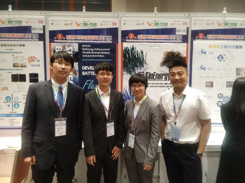 Poster session, Hong Kong competition (2019). The poster reads “Develop Ni-MH battery to be flexible”.
5.1 The business logic
- Customer and product. Wristbands, watch straps and entertainment props first (a safe, flexible, waterproof, possibly self-charging band); later, B2B cells for other wearable makers; longer term, medical and military wearables.
- Industrial strategy: reuse, do not reinvent. Start with electrodes bought from an existing cylindrical Ni–MH manufacturer (they do raw material, Ni foam and steel mesh substrates, coating, rolling, drying, tab welding). We then only add the flexible packaging and structure. That cuts first-product capital and time.
- Three-tier plan. Upstream: production-line design and retrofit. Midstream: sell flexible cells and electrode sheets B2B. Downstream: own-brand wearable products.
- Roadmap (proposal). 2018–2019 research (first-generation packaging, low-cost electrode, flexible nickel paper); 2019–2020 trial on a conventional line (coating, packaging); 2020–2023 product iterations, ending in a self-charging band.
5.2 A cost model, and a number I do not trust
The proposal gives a first-pass margin for a wristband made on existing lines (cost per 100 units about 197.5–199.5 CNY; selling price 39.9 CNY each, so 3990 CNY per 100; “gross profit 3790 CNY per 100”), against competing bands at 9.9 CNY (disposable battery) and 29.9 CNY (rechargeable battery).
Check. The itemised lines are electrode material 57, energy-conversion film 20, packaging and other 20 (sum 97), plus labour 3.5–5.7 per 100 units, giving about 101–103 CNY per 100, not 197.5–199.5. The difference of roughly 95–98 CNY is not itemised in the document I have. The margin arithmetic itself ($3990 - 199.5 = 3790.5$) is fine, but the page should not claim a cost of about 200 CNY per 100 units until the missing line is identified. I recommend treating this as an unreconciled assumption in any further pitch.
5.3 Risk thinking
The proposal separates technical risk (low: prototypes exist, funding and awards received), market risk (price is high at first because few suppliers exist; no substitute product yet; first-mover and patent protection), and mitigation (partnering with an established manufacturer; protecting core IP via Chinese and US patents and papers; attention to key-staff turnover). It names patent filing (applicant: CityU Shenzhen Research Institute) and journal submission as parallel tracks, which is the usual academic-to-industry split.
5.4 What the competitions taught
The same work was presented in three different formats: a poster session and pitch in Hong Kong, a business-plan finals in Hangzhou, and a technical-works exhibition at the Challenge Cup in Beijing. Each format rewards a different emphasis (clear problem and prototype; business model and scale-up path; depth of science and live demonstration), so the same story had to be re-cut each time.
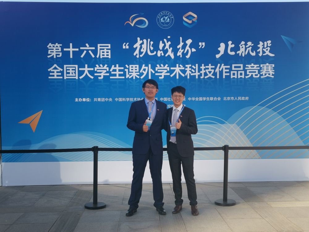 National Finals of the 16th “Challenge Cup”, Beihang University, Beijing.
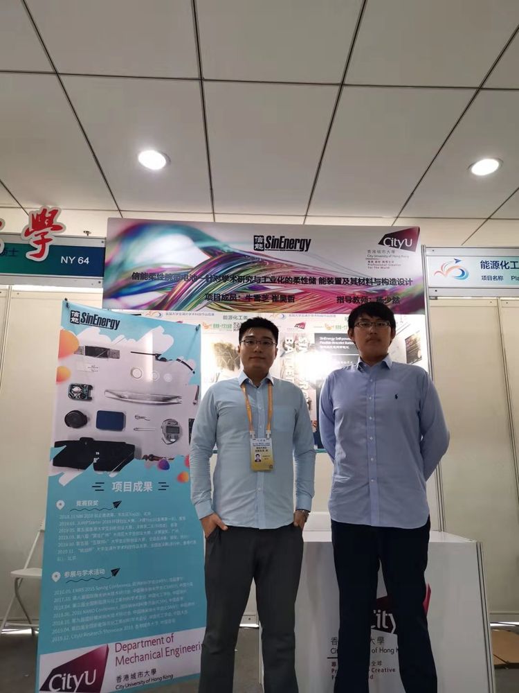 The SinEnergy exhibition booth at the Challenge Cup finals.
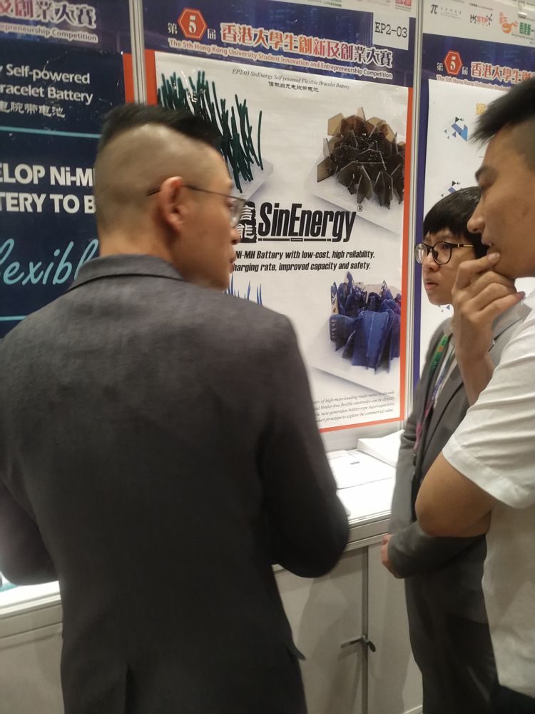 Explaining the product to a visitor at the Hong Kong competition.
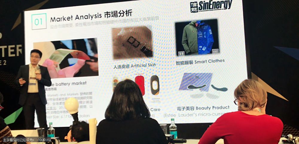 Pitching the market analysis.
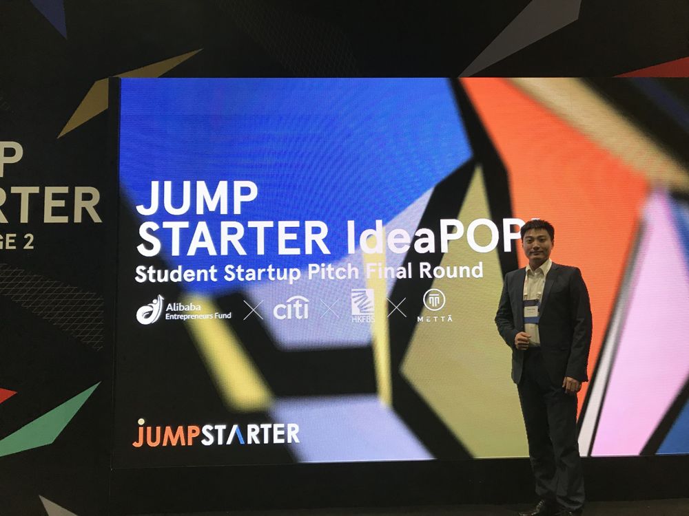 The JUMPStarter start-up pitch.
6. What I took away, and what is not yet documented
Engineering lessons.
- Pick the platform the factory already runs. Chemistry that wins on paper and cannot be coated on an existing line loses in industry.
- Design for the failure mode that matters (cracking under bending, leaking under sweat), and let that choose materials and structure, not the other way round.
- Say the weakness out loud (low energy density, power-class discharge) and design the product around it.
- Reconcile your own numbers before a jury does; the cost model above is an example of where I would now check first.
Open items (honest list).
- The assembly die and fixture drawing is not in the materials available to me (Section 2.4).
- My exact role is stated at a high level only (“structural and product side, and entrepreneurship”). If a more specific list (which parts I designed or built, which tests I ran) is wanted, I should add it from my own records rather than infer it.
- The cost reconciliation in Section 5.2.
- The self-charging Type III device is described as in research; the proposal gives the PZT-foam fabrication recipe (PZT sol, 30% Pb excess, sintering at 1000 °C, PDMS infiltration, silver electrodes, poling at 15 kV mm$^{-1}$) but no output data, so I have not claimed any.
Sources: SinEnergy project proposal (Chinese, 2019); TSANG Ying, final year report, City University of Hong Kong, 2018; City University of Hong Kong MNE news items on the competitions (2019); team photographs.